本来は、lidarで取得するpcd(点群データ)をdepth画像から作成する手順。
理由はlidarからだと綺麗なpcdが撮影できない感じがしたから。
なのでdepth画像とrgb画像を合わせてpcdを作ることにした。
目次
1. lidarから直接pcdを作成する
2. depth画像とrgb 画像からpcdを作成する
3. PCLで両方のpcdを比較してみる
1. lidarから直接pcdを作成する
pcd(点群データ)のtopic名は/camera/depth/color/points。
まず、lidarで表示。
pcdをlidarに表示させるのは普通にlaunchする時に、filters:=pointcloudを引数にとる。
$ roslaunch realsense2_camera rs_camera.launch filters:=pointcloud
$ roslaunch realsense2_camera demo_pointcloud.launch
$ rosrun image_view image_view image:=/camera/color/image_raw
$ rosbag record -O /home/parallels/place/pcd.bag /camera/depth/color/points
$ rosbag info pcd.bag
bagからpcdを作成
$ roscore
$ rosrun pcl_ros bag_to_pcd pcd.bag /camera/depth/color/points /home/parallels/place/pcds
pcdファイルが保存先フォルダに山のように保存される。
$ du -k 1647787135.031567812.pcd
1ファイル1MBを超えるのでなかなか重い
2. depth画像とrgb 画像からpcdを作成する
depth画像とrgb画像の作成は過去記事参照。
trafalbad.hatenadiary.jp
depth画像とrgb画像をペアで一つのpcdファイルを作成する。
ライブラリはopen3Dというのを使う。
セットアップ
$ pip3 install open3d
$ catkin_create_pkg pcd_create roscpp rospy std_msgs cv_bridge image_transport message_generation
$ sudo vi CMakeLists.txt
$ cd ~/catkin_ws && catkin_make
CMakeLists.txt(以下を追記)
find_package(PCL 1.8 REQUIRED)
include_directories(
  include
  ${catkin_INCLUDE_DIRS}
  ${PCL_INCLUDE_DIRS}
)
add_executable(vccs
  src/vccs.cpp
)
target_link_libraries(vccs
  ${catkin_LIBRARIES}
  ${PCL_LIBRARIES}
)
depth画像とrgb画像からpcdの作成
$ roslaunch realsense2_camera rs_camera.launch filters:=pointcloud
$ rosrun image_view image_view image:=/camera/color/image_raw
$ rosbag record -O /home/parallels/place/depth.bag /camera/color/image_raw /camera/depth/image_rect_raw
$ python3 rosbag2depth.py
$ python3 depth2pcd.py
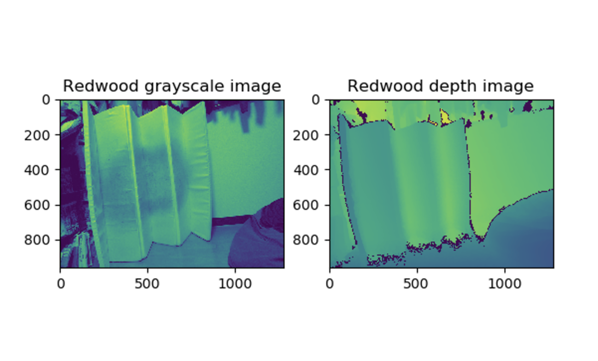
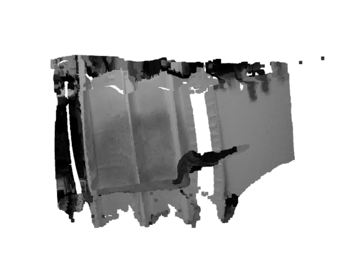
結果(RGB/depth)
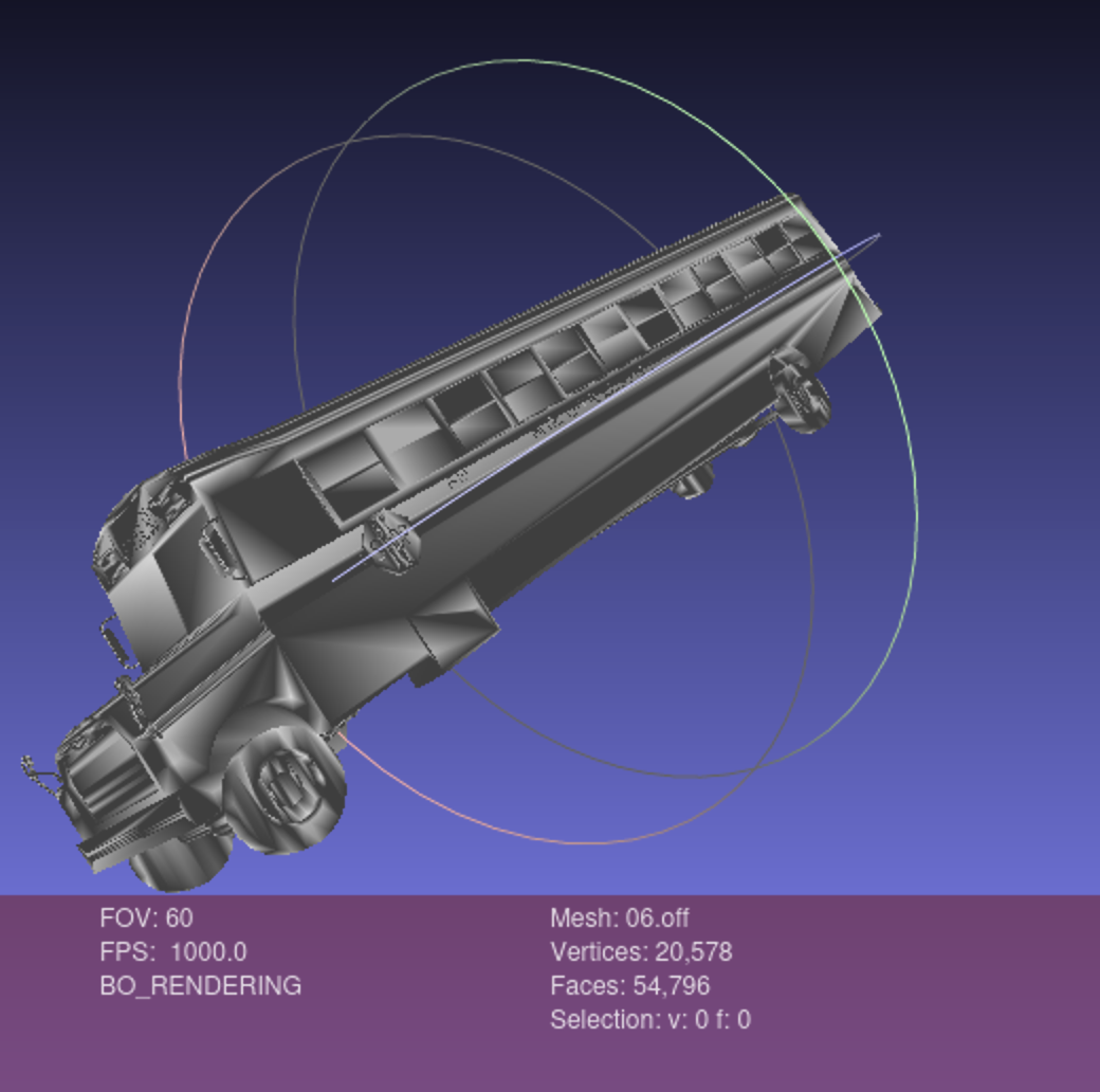
作成したPCD
depth2pcd.py(pcd作成スクリプト)
import open3d as o3d
import matplotlib.pyplot as plt
import os
def main(out_dir, plot=False):
color_raw = o3d.io.read_image(os.path.join(out_dir, "rgb/frame000001.jpg"))
depth_raw = o3d.io.read_image(os.path.join(out_dir, "depth/frame000000.png"))
rgbd_image = o3d.geometry.RGBDImage.create_from_color_and_depth(
color_raw, depth_raw)
if plot:
plt.subplot(1, 2, 1)
plt.title('Redwood grayscale image')
plt.imshow(rgbd_image.color)
plt.subplot(1, 2, 2)
plt.title('Redwood depth image')
plt.imshow(rgbd_image.depth)
plt.show()
pcd = o3d.geometry.PointCloud.create_from_rgbd_image(
rgbd_image,
o3d.camera.PinholeCameraIntrinsic(
o3d.camera.PinholeCameraIntrinsicParameters.PrimeSenseDefault))
pcd.transform([[1, 0, 0, 0], [0, -1, 0, 0], [0, 0, -1, 0], [0, 0, 0, 1]])
o3d.visualization.draw_geometries([pcd])
o3d.io.write_point_cloud(os.path.join(out_dir, "open3d.pcd"), pcd)
if __name__ == "__main__":
out_dir = '/home/parallels/place'
main(out_dir, plot=True)
3. PCLで両方のpcdを比較してみる
pcl
チュートリアルにある
クラスタリング(SupervoxelClustering)で
pcdの出来を確認してみる。
pcl::SupervoxelClusteringを使用するとpointcloudを複数のsupervoxel clustersに分割できる
XYZ座標系の情報
| コード |
説明 |
PointXYZ
| 点群3D位置情報のみ取得
|
PointXYZRGB
| 点群3Dの位置情報にRGBの色をつけて取得 |
PointXYZRGBA
| 点群3D位置情報にRGBAの色情報をつけて取得(Aは透明度Alpha)
|
PointXYZI
| 点群3D位置情報に輝度の色情報をつけて取得
|
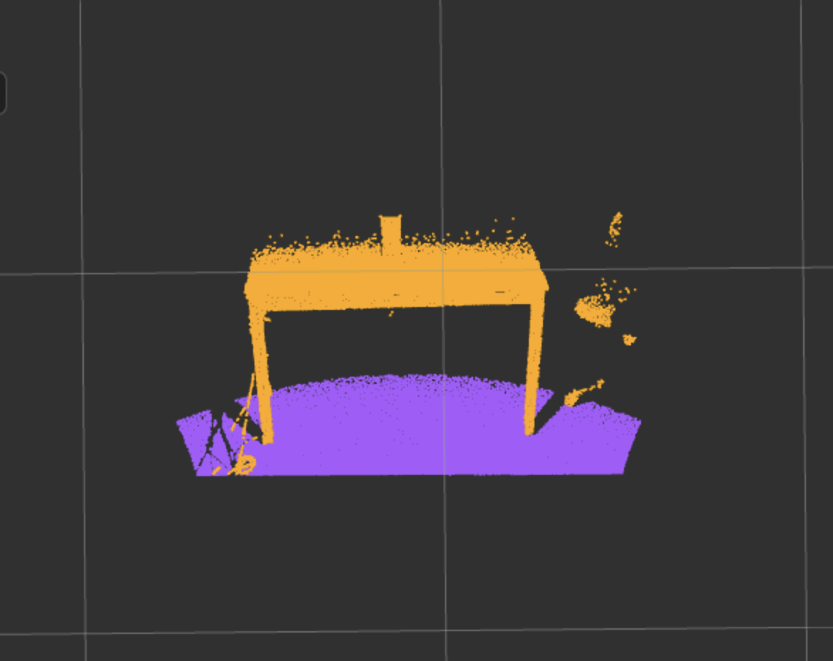
PCLで確認してみる
Lidarから取得したPCD
$ rosrun pcd_create vccs /home/usr/pcd/1647790156.662197590.pcd
depthとrgbから作成したPCD
$ rosrun pcd_create vccs /home/usr/open3d.pcd
直接Lidarから取得した方出来がいいようだ。
実例でもdepthから作ってるの聞いたことないし、直接撮影した方が綺麗にできそう。PCDのテクはまだ不明なことが多い。
確認用スクリプト(src/vccs.cpp)
#include <pcl/console/parse.h>
#include <pcl/point_cloud.h>
#include <pcl/point_types.h>
#include <pcl/io/pcd_io.h>
#include <pcl/visualization/pcl_visualizer.h>
#include <pcl/segmentation/supervoxel_clustering.h>
#include <vtkPolyLine.h>
typedef pcl::PointXYZRGBA PointT;
typedef pcl::PointCloud<PointT> PointCloudT;
typedef pcl::PointNormal PointNT;
typedef pcl::PointCloud<PointNT> PointNCloudT;
typedef pcl::PointXYZL PointLT;
typedef pcl::PointCloud<PointLT> PointLCloudT;
void addSupervoxelConnectionsToViewer (PointT &supervoxel_center,
PointCloudT &adjacent_supervoxel_centers,
std::string supervoxel_name,
pcl::visualization::PCLVisualizer::Ptr & viewer);
int
main (int argc, char ** argv)
{
if (argc < 2)
{
pcl::console::print_error ("Syntax is: %s <pcd-file> \n "
"--NT Dsables the single cloud transform \n"
"-v <voxel resolution>\n-s <seed resolution>\n"
"-c <color weight> \n-z <spatial weight> \n"
"-n <normal_weight>\n", argv[0]);
return (1);
}
PointCloudT::Ptr cloud (new PointCloudT);
pcl::console::print_highlight ("Loading point cloud...\n");
if (pcl::io::loadPCDFile<PointT> (argv[1], *cloud))
{
pcl::console::print_error ("Error loading cloud file!\n");
return (1);
}
bool disable_transform = pcl::console::find_switch (argc, argv, "--NT");
float voxel_resolution = 0.008f;
bool voxel_res_specified = pcl::console::find_switch (argc, argv, "-v");
if (voxel_res_specified)
pcl::console::parse (argc, argv, "-v", voxel_resolution);
float seed_resolution = 0.1f;
bool seed_res_specified = pcl::console::find_switch (argc, argv, "-s");
if (seed_res_specified)
pcl::console::parse (argc, argv, "-s", seed_resolution);
float color_importance = 0.2f;
if (pcl::console::find_switch (argc, argv, "-c"))
pcl::console::parse (argc, argv, "-c", color_importance);
float spatial_importance = 0.4f;
if (pcl::console::find_switch (argc, argv, "-z"))
pcl::console::parse (argc, argv, "-z", spatial_importance);
float normal_importance = 1.0f;
if (pcl::console::find_switch (argc, argv, "-n"))
pcl::console::parse (argc, argv, "-n", normal_importance);
pcl::SupervoxelClustering<PointT> super (voxel_resolution, seed_resolution);
if (disable_transform)
super.setUseSingleCameraTransform (false);
super.setInputCloud (cloud);
super.setColorImportance (color_importance);
super.setSpatialImportance (spatial_importance);
super.setNormalImportance (normal_importance);
std::map <std::uint32_t, pcl::Supervoxel<PointT>::Ptr > supervoxel_clusters;
pcl::console::print_highlight ("Extracting supervoxels!\n");
super.extract (supervoxel_clusters);
pcl::console::print_info ("Found %d supervoxels\n", supervoxel_clusters.size ());
pcl::visualization::PCLVisualizer::Ptr viewer (new pcl::visualization::PCLVisualizer ("3D Viewer"));
viewer->setBackgroundColor (0, 0, 0);
PointCloudT::Ptr voxel_centroid_cloud = super.getVoxelCentroidCloud ();
viewer->addPointCloud (voxel_centroid_cloud, "voxel centroids");
viewer->setPointCloudRenderingProperties (pcl::visualization::PCL_VISUALIZER_POINT_SIZE,2.0, "voxel centroids");
viewer->setPointCloudRenderingProperties (pcl::visualization::PCL_VISUALIZER_OPACITY,0.95, "voxel centroids");
PointLCloudT::Ptr labeled_voxel_cloud = super.getLabeledVoxelCloud ();
viewer->addPointCloud (labeled_voxel_cloud, "labeled voxels");
viewer->setPointCloudRenderingProperties (pcl::visualization::PCL_VISUALIZER_OPACITY,0.8, "labeled voxels");
PointNCloudT::Ptr sv_normal_cloud = super.makeSupervoxelNormalCloud (supervoxel_clusters);
pcl::console::print_highlight ("Getting supervoxel adjacency\n");
std::multimap<std::uint32_t, std::uint32_t> supervoxel_adjacency;
super.getSupervoxelAdjacency (supervoxel_adjacency);
for (auto label_itr = supervoxel_adjacency.cbegin (); label_itr != supervoxel_adjacency.cend (); )
{
std::uint32_t supervoxel_label = label_itr->first;
pcl::Supervoxel<PointT>::Ptr supervoxel = supervoxel_clusters.at (supervoxel_label);
PointCloudT adjacent_supervoxel_centers;
for (auto adjacent_itr = supervoxel_adjacency.equal_range (supervoxel_label).first; adjacent_itr!=supervoxel_adjacency.equal_range (supervoxel_label).second; ++adjacent_itr)
{
pcl::Supervoxel<PointT>::Ptr neighbor_supervoxel = supervoxel_clusters.at (adjacent_itr->second);
adjacent_supervoxel_centers.push_back (neighbor_supervoxel->centroid_);
}
std::stringstream ss;
ss << "supervoxel_" << supervoxel_label;
addSupervoxelConnectionsToViewer (supervoxel->centroid_, adjacent_supervoxel_centers, ss.str (), viewer);
label_itr = supervoxel_adjacency.upper_bound (supervoxel_label);
}
while (!viewer->wasStopped ())
{
viewer->spinOnce (100);
}
return (0);
}
void
addSupervoxelConnectionsToViewer (PointT &supervoxel_center,
PointCloudT &adjacent_supervoxel_centers,
std::string supervoxel_name,
pcl::visualization::PCLVisualizer::Ptr & viewer)
{
vtkSmartPointer<vtkPoints> points = vtkSmartPointer<vtkPoints>::New ();
vtkSmartPointer<vtkCellArray> cells = vtkSmartPointer<vtkCellArray>::New ();
vtkSmartPointer<vtkPolyLine> polyLine = vtkSmartPointer<vtkPolyLine>::New ();
for (auto adjacent_itr = adjacent_supervoxel_centers.begin (); adjacent_itr != adjacent_supervoxel_centers.end (); ++adjacent_itr)
{
points->InsertNextPoint (supervoxel_center.data);
points->InsertNextPoint (adjacent_itr->data);
}
vtkSmartPointer<vtkPolyData> polyData = vtkSmartPointer<vtkPolyData>::New ();
polyData->SetPoints (points);
polyLine->GetPointIds ()->SetNumberOfIds(points->GetNumberOfPoints ());
for(unsigned int i = 0; i < points->GetNumberOfPoints (); i++)
polyLine->GetPointIds ()->SetId (i,i);
cells->InsertNextCell (polyLine);
polyData->SetLines (cells);
viewer->addModelFromPolyData (polyData,supervoxel_name);
}
参考サイト
・
Open3D
・
Open3D+ROS+Pythonで3次元画像処理を楽々プロトタイピング
・
ROSでPCLのサンプルを動かす - supervoxel clustering